
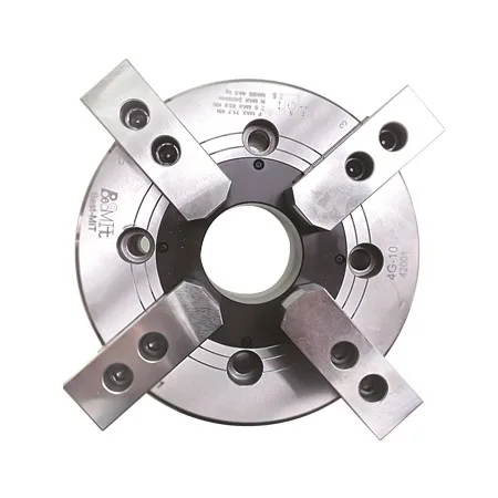
The Wedge-Shaped Power Chuck with 3 Claws and the Super-Large Through-Hole Diameter.
The sliding surface is hardened, precision grinded and directly lubricated.
High-Rigidity Structure and High-Clamping Accuracy.
The J value is the hole diameter of an un-threaded coupling nut, and the L value is the maximum-size specification allowed for a coupling nut's thread machining operation, but they can be customized according to actual needs.
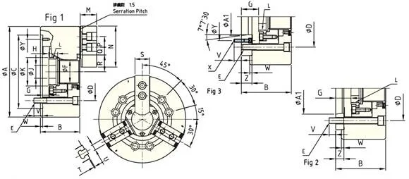
External Dimensions:
|
Dimensions Model Type |
A | B | C | D | E | F |
G Max |
G Min |
H | J | K | L |
|---|---|---|---|---|---|---|---|---|---|---|---|---|
| 3B(D)-04 | 110 | 59 | 85 | 70.6 | 3-M10 | 26 | 3.5 | -6.5 | 17.5 | 12 | 38 | M32x1.5 |
| 3B(D)-05 A4 | 135 |
60 71 |
110 | 82.6 | 3-M10 | 33 |
1 16 |
-9 6 |
20 | 12 | 45 | M40x1.5 |
| 3B(D)-06 A5 | 168 |
81 91 |
140 | 104.8 | 6-M10 | 45 |
11 26 |
-1 14 |
19 | 20 | 60 | M55x2.0 |
| 3B(D)-08 A6 | 210 |
91 103 |
170 | 133.4 | 6-M12 | 52 |
14.5 31.5 |
-1.5 15.5 |
20.5 | 30 | 66 | M60x2.0 |
| 3B(D)-10 A6 | 254 |
100 120 |
220 | 171.4 | 6-M16 | 75 |
8.5 33.5 |
-10.5 -14.5 |
25 | 45 | 94 | M85x2.0 |
| 3B(D)-10 A8 | 254 |
100 113 |
220 | 171.4 | 6-M16 | 75 |
8.5 26.5 |
-10.5 7.5 |
25 | 45 | 94 | M85x2.0 |
| 3B(D)-12 A6 | 304 |
110 129 |
220 | 133.4 | 6-M16 | 91 |
8 33 |
-15 10 |
28 | 50 | 108 | M90x2.0 |
| 3B(D)-12 A8 | 304 |
110 122 |
220 | 171.4 | 6-M16 | 91 |
8 26 |
-15 3 |
28 | 50 | 108 | M100x2.0 |
|
Dimensions Model Type |
M | N | P |
Q Max |
Q Min |
R Max |
R Min |
S | T | U | V | W |
|---|---|---|---|---|---|---|---|---|---|---|---|---|
| 3B(D)-04 | 24 | 52 | 14 | 11.25 | 6.75 | 23 | 20.3 | 23 | 2 | 10 | 16 | 4 |
| 3B(D)-05 A4 | 31 | 62 | 14 | 19.75 | 7.75 | 26.5 | 23.8 | 25 | 2 | 10 | 15 | 4 |
| 3B(D)-06 A5 | 37 | 73 | 20 | 22.75 | 9.25 | 32 | 29.25 | 31 | 2 | 12 | 16 | 5 |
| 3B(D)-08 A6 | 38 | 95 | 25 | 29.75 | 14.75 | 38.7 | 35 | 35 | 2 | 14 |
20 18 |
5 |
| 3B(D)-10 A6 | 43 | 110 | 30 | 33.75 | 14.25 | 51 | 46.6 | 40 | 2 | 16 |
22 18 |
5 |
| 3B(D)-10 A8 | 43 | 110 | 30 | 33.75 | 14.25 | 51 | 46.6 | 40 | 2 | 16 |
22 24 |
5 |
| 3B(D)-12 A6 | 51 | 130 | 30 | 45.75 | 15.75 | 61.3 | 56 | 50 | 2 | 21 |
23 18.5 |
6 |
| 3B(D)-12 A8 | 51 | 130 | 30 | 45.75 | 15.75 | 61.3 | 56 | 50 | 2 | 21 |
23 25 |
6 |
|
Dimensions Model Type |
X | Y | Z | A1 | Fig | |||||||
|---|---|---|---|---|---|---|---|---|---|---|---|---|
| 3B(D)-04 | - | - | - | - | 1 | |||||||
| 3B(D)-05 A4 | 3-M6 | - | 15 | 63.51 | 2 | |||||||
| 3B(D)-06 A5 | 3-M6 | - | 15 | 82.56 | 2 | |||||||
| 3B(D)-08 A6 | 3-M6 | - | 17 | 106.38 | 2 | |||||||
| 3B(D)-10 A6 | 6-M12 | 133.4 | 25 | 106.38 | 3 | |||||||
| 3B(D)-10 A8 | 3-M8 | - | 18 | 139.72 | 2 | |||||||
| 3B(D)-12 A6 | 6-M12 | 133.4 | 25 | 106.38 | 3 | |||||||
| 3B(D)-12 A8 | 3-M8 | - | 18 | 139.72 | 2 |
Technical Specifications:
|
Dimensions Model Type |
Plunger stroke[mm] |
Claw Stroke (Diameter) [mm] |
Clamping Diameter [mm] |
Maximum Allowable Force KN(kgf) |
|
|---|---|---|---|---|---|
| Max | Min | ||||
| 3B(D)-04 | 10 | 5.4 | 110 | 7 | 14.0 (1400) |
| 3B(D)-05 A4 | 10 | 5.4 | 135 | 12 | 17.5 (1700) |
| 3B(D)-06 A5 | 12 | 5.5 | 169 | 16 | 22.0 (2200) |
| 3B(D)-08 A6 | 16 | 7.4 | 210 | 13 | 34.3 (3500) |
| 3B(D)-10 A6 | 19 | 8.8 | 254 | 31 | 43.0 (4300) |
| 3B(D)-10 A8 | 19 | 8.8 | 254 | 31 | 43.0 (4300) |
| 3B(D)-12 A6 | 23 | 10.6 | 304 | 34 | 54.9 (5600) |
| 3B(D)-12 A8 | 23 | 10.6 | 304 | 34 | 54.9 (5600) |
|
Dimensions Model Type |
Maximum Clamping Force KN(kgf) |
Maximum Rotating Speed [rpm] |
I Kg. m2 |
Weight [Kg] |
Associate Rotary Cylinder | Maximum Working Pressure(kg/cm2) |
|---|---|---|---|---|---|---|
| 3B(D)-04 | 28.4 (2900) | 8000 | 0.01 | 4 | CT-533 | 2.3 (23) |
| 3B(D)-05 A4 | 35.8 (3600) | 7000 | 0.02 |
6.7 7.5 |
CT-533 | 2.9 (29) |
| 3B(D)-06 A5 | 56.8 (5800) | 6000 | 0.06 |
11.9 13.7 |
CT-646 | 2.8 (28) |
| 3B(D)-08 A6 | 85.8 (8755) | 5000 | 0.17 |
22.5 23.6 |
CT-852 | 2.8 (28) |
| 3B(D)-10 A6 | 111.0 (11300) | 4200 | 0.3 |
34.5 41.5 |
CT-1075 | 2.7 (27) |
| 3B(D)-10 A8 | 111.0 (11300) | 4200 | 0.3 |
34.5 40 |
CT-1075 | 2.7 (27) |
| 3B(D)-12 A6 | 144.0 (14600) | 3300 | 0.7 |
56.6 67 |
CT-1291 | 2.7 (27) |
| 3B(D)-12 A8 | 144.0 (14600) | 3300 | 0.7 |
56.6 64 |
CT-1291 | 2.7 (27) |
※ The company produces chucks with adjustable structures for balancing that their I value can be adjusted.